Key Takeaways
- Full jar line automation is a connected sequence of stations, so throughput and quality depend on matching speeds, spacing, and handoffs across the entire flow—not optimizing one machine in isolation.
- Defining targets upfront for OEE, downtime, and changeovers shapes equipment choices, because recipe-driven controls and modular tooling only deliver big time savings when they’re built into the design.
- Stable empty-jar infeed is the foundation for the whole line, making the right unscrambler/orientation approach, container-friendly conveyors, and properly sized accumulation critical for preventing jams.
- Filling and capping performance is driven by product and closure realities, so selecting the correct filler type, controlling foaming/drip contamination, and using torque trending and sealing stations prevents leaks and downstream label failures.
- Successful automation requires a structured integration process—site survey, layout, and equipment selection for future SKUs, deterministic controls and safety, FAT/SAT validation with reject testing, and a maintenance/spares plan that protects uptime after go-live.
Jar line automation turns a manual, labor-intensive process into a synchronized system that moves product from bulk empty containers to shelf-ready units without hand intervention. A well-designed packaging line flow links every station—infeed to palletizer—so speed, quality, and output targets are hit consistently across every shift. Getting there requires understanding what each station does, what performance benchmarks to set before buying anything, and what product details lock in the design. This article answers those questions directly, section by section, so manufacturers evaluating automation integration have a clear picture before committing capital.
What Does "Full Jar Packaging Line Automation" Include From Start to Finish?
Full jar line automation is not a single machine. It is a connected sequence of stations, each one feeding the next at matched speeds. A failure to define the system as a whole—before specifying any individual piece of equipment—is the most common reason lines underperform after installation.
What Are the Core Stations From Infeed to End-of-Line?
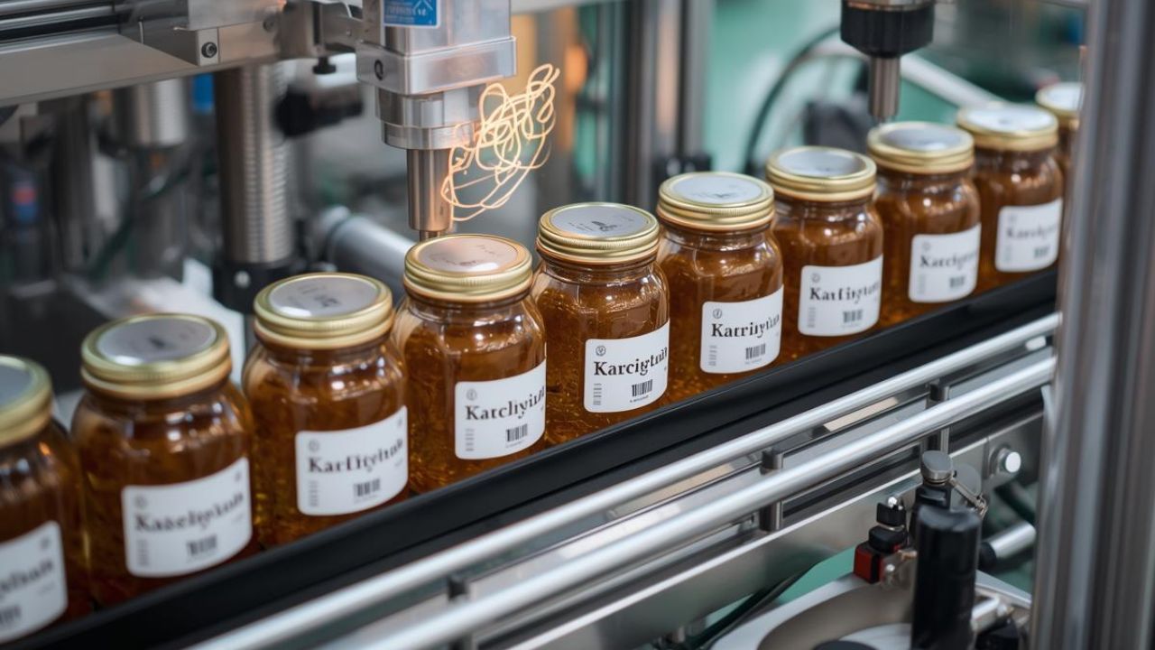
A complete packaging line flow runs six to eight stations in sequence: unscrambling and orienting, conveyor transport and accumulation, cleaning, filling, capping and sealing, vision inspection, labeling on jars, and end-of-line case packing and palletizing.
Unscrambling systems at the head of the line handle 30 to 300 jars per minute, depending on jar size and technology. Each station hands off to the next through synchronized conveyors. Speed mismatches between any two stations are the primary source of jams, rejects, and lost OEE—so automation integration is a line-level problem, not a machine-level one.
What Performance Goals Should You Define First?
Set your targets before you spec equipment, not after. Baseline OEE on manually supported lines runs 65–75%. Well-integrated automated jar lines reach 85%+ within 18 months of commissioning. Unplanned downtime drops 40–60% when predictive maintenance is built into the control architecture from the start.
Changeover time is equally important to define upfront. Recipe-driven HMIs and modular tooling can cut changeover by 50–70%—but only if the target was a design requirement. If it is discovered after installation, it becomes an expensive retrofit.
What Jar, Lid, and Product Details Determine Line Design?
Empty jar handling, filling technology, and capping equipment are all determined by the product and container—not the other way around. Viscosity, particulate size, and fill temperature (hot-fill vs. cold-fill) dictate which filler type is viable and whether a cooling tunnel is required downstream of the capper.
Closure type drives the capping station selection. Continuous thread, lug cap, child-resistant, and induction-sealed liners each require different heads, torque ranges, and potentially additional stations such as tamper-evident banding. Document these details before any layout is drawn. Changes found after equipment purchase are the single most common cause of automation integration cost overruns.
How Do You Automate Empty Jar Handling and Infeed Without Jams?
Infeed is where most jam problems originate. Empty jar handling sets the pace for everything downstream—if jars arrive unstable, misoriented, or unevenly spaced, every subsequent station pays the price. Getting this section right means selecting the correct unscrambling technology, specifying conveyors that protect containers, and deciding upfront whether cleaning is required before filling.
How Do Unscramblers, Denesters, and Orienters Keep Jars Stable and Correctly Spaced?
Centrifugal and inline unscramblers both accept bulk jars and deliver them upright and singulated. Centrifugal units use a spinning disc to self-sort containers at higher speeds. Inline unscramblers handle more fragile or irregular geometries at controlled rates. The choice depends on jar shape, fragility, and target throughput within the 30–300 jars per minute industry range.
Orientation follows unscrambling. Mechanical pockets, vision-guided air jets, and servo-controlled timing gates each ensure jars arrive at the filler in the same rotational position every cycle. This is non-negotiable for embossed containers, handled jars, or any shape where fill nozzle alignment matters.
What Conveyor Features Prevent Tipping and Scuffing?
Conveyor specs must match jar dimensions and line speed precisely. Systems span lengths from 960 to 12,000 mm and widths from 254 to 1,219 mm, with speeds reaching up to 183 m/min—enough range to accommodate nearly any jar line configuration. Belt selection matters as much as dimensions. Sponge rubber belts with PVC fabric facing grip containers gently, prevent scuffing, and keep jars stable at higher speeds where standard flat belts lose control of the product.
Accumulation tables and zero-pressure conveyors at the infeed buffer brief downstream stoppages without halting the unscrambler. That buffer is what keeps packaging line flow continuous when a downstream station momentarily pauses—without it, the entire infeed section stops and restarts, compounding the original fault.
When Should You Add Cleaning or Ionized Air Rinsing Before Filling?
For food applications, ionized air rinsing is the standard pre-fill step. It removes particulates and static charge from the interior of jars immediately before the filling station, preventing contamination without adding water, drying time, or additional footprint to the line.
Water rinsing and sterilization are reserved for regulatory requirements or products with microbial sensitivity. These add meaningful complexity—drying sections, drainage, and extended line length—that must be planned into the layout from the start. Adding them as an afterthought disrupts line spacing and frequently forces a redesign of the infeed section.
How Do You Automate Filling Accurately for Liquids, Sauces, Powders, or Chunky Products?
Filling is the most product-dependent station on the line. The wrong filler type produces inconsistent fills, excessive waste, and downstream problems at capping and labeling. Getting it right means matching the technology to the product's physical properties—then adding the in-process checks that catch errors before they compound.
Which Filling Technology Fits Your Product?
Filler selection is dictated by what you are filling, not by preference.
Piston fillers handle thick sauces, pastes, and chunky products with consistent volumetric doses. Net weight fillers are the right choice when regulatory requirements or label claims demand mass accuracy. Auger fillers meter free-flowing powders reliably. Time-pressure and pump fillers suit thin, stable liquids where speed and simplicity are the priorities.
Headspace control applies to all of them. The gap between the product surface and the lid is a required specification for food and beverage applications—it affects preservation shelf life and determines whether an induction seal will bond correctly. Specify it before the filler is ordered, not during commissioning.
How Do You Control Foaming, Dripping, and Stringing to Protect Downstream Capping and Labeling?
Contamination at the jar neck during filling causes failures at every station that follows. Foam left on the neck creates capping torque inconsistencies and label adhesion failures at the labeling on jars station. Bottom-up fill nozzles, slow-start flow profiles, and nozzle geometry matched to the product's surface tension are the standard controls for foaming products.
Dripping and stringing are managed with drip-back nozzles, timed shutoffs, and anti-drip valves. These prevent the product from reaching the jar exterior before capping. A clean exterior is not an aesthetic concern—it is a prerequisite for consistent label adhesion and reliable torque readings across shifts.
What In-Process Checks Reduce Waste?
Inline checkweighers placed immediately after the filler are the highest-value quality checkpoint on the line. An out-of-spec jar caught here costs only the product. The same jar caught after capping, labeling, and case packing costs the cap, label, case materials, and labor for every station it passes through.
Vision inspection systems run parallel to the line, verifying fill level, cap presence, and label quality at full line speed. Reject mechanisms respond automatically—air-blow ejectors handle lightweight jars, diverter arms handle heavier containers. Both protect the packaging line flow by removing non-conforming product without stopping the line or requiring manual intervention.
How Do You Automate Capping and Sealing While Preventing Leaks and Consumer Complaints?
Capping is where fill integrity becomes package integrity. A missed cap, undertorqued closure, or failed seal reaches the consumer—and every one of those failures is traceable back to a decision made during line design. The right cap feeding system, torque controls, and sealing station configuration prevent those failures before they leave the facility.
What Cap Feeding and Placement Options Reduce Miscaps?
Caps must be oriented and singulated before they reach the capping head. Vibratory bowls, elevators, and chutes each accomplish this at different speeds and for different cap geometries. The feeding system is matched to cap size, shape, and line speed—a mismatch here is a direct cause of miscaps and jams at the capper.
Pick-and-place robotic cappers add a different kind of value: flexibility. For multi-SKU lines where cap sizes change between runs, a robotic capper handles format changes through programming rather than mechanical tooling swaps. On high-volume single-SKU lines, a conventional inline capper running a matched vibratory bowl system is faster and simpler.
How Do You Control Torque and Seal Integrity Across Shifts?
Torque monitoring tracks two separate measurements. Application torque is the force used to drive the cap during sealing. Removal torque is what the consumer experiences when opening—and what regulators and retailers use to verify seal integrity. Both must be within specification, and they do not always move together.
Trend data and alarms are what turn torque monitoring from a record-keeping function into a preventive tool. Drift in application torque flagged by an alarm mid-shift, stops a defective run before thousands of units are produced. Without trending, torque problems are discovered during audits or, worse, through consumer complaints.
When Do Tamper-Evident Bands, Induction Seals, or Vacuum Lug Caps Change the Automation Plan?
Closure type determines whether capping is one station or three. Each sealing format adds specific equipment, footprint, and thermal considerations that must be planned into the line layout before installation.
Choose induction sealing when a foil liner tamper-evident closure is required. It adds a dedicated station using an electromagnetic field to bond the liner to the jar rim without contact, plus additional conveyor length, power supply routing, and a cooling section before jars can be handled downstream.
Choose vacuum lug caps when an audible safety button is a product or regulatory requirement. This adds a steam or vacuum tunnel and modifies torque application profiles across the capping station.
Choose tamper-evident banding when full-perimeter visual evidence of first open is required. A heat-shrink tunnel is added after capping, and its thermal output must be accounted for before the labeling on jars station, since residual heat degrades pressure-sensitive adhesive performance and compromises automation integration between sealing and labeling.
What Steps Are Involved in Automating a Full Jar Packaging Line?
Jar line automation is a process, not a purchase. The difference between a line that hits its targets on day one and one that underperforms for months is how thoroughly the work was done before any equipment was ordered. Site conditions, control architecture, validation protocol, and maintenance planning are all decided in sequence—and each one constrains the next.
How Do You Map the Current Workflow and Constraints?
A pre-integration site survey is the first deliverable. It documents available floor space, ceiling height, utility drops (power, compressed air, water), and the exact position of existing upstream and downstream equipment. These constraints are not negotiable after the fact—they determine where every station can physically go and what connections are possible.
Staffing and shift structure belong in this survey, too. Automation integration decisions—how much to automate, where to leave manual assist points, how many operators the line requires—are all informed by current labor costs and future headcount targets. Mapping the current state fully is what makes the future state achievable.
How Do You Select Equipment and Line Layout to Match Throughput and Future SKUs?
Equipment selection follows the site survey. Modular designs allow capacity to expand by adding stations or lanes rather than replacing entire lines—a critical advantage for operations that expect SKU growth or volume increases within a three-to-five year window. Phased investment is only possible if modularity was specified from the start. For operations earlier in the investment cycle, our guide to affordable packaging automation outlines how smaller manufacturers approach phased line buildouts.
Communication protocol selection is equally forward-looking. Equipment purchased with open protocols—OPC UA, Modbus TCP, MQTT—can connect to MES, ERP, and advanced analytics platforms later without costly retrofits. Closed or proprietary protocols lock the line into the vendor's ecosystem and limit future packaging line flow optimization.
How Do You Integrate Controls and Safety?
Control architecture determines how well the line runs as a system. EtherNet/IP and PROFINET both support data rates up to 1,000 Mbps with cycle times below 1 ms—either is suitable for synchronized motion control across filling, capping, and labeling stations. Modbus TCP, running at up to 115.2 Kbps with 10–50 ms cycle times, handles simpler status monitoring tasks where high-speed determinism is not required.
PackML and OPC UA standards reduce multi-vendor integration engineering time by providing common state machine definitions across equipment from different manufacturers. At the actuator level, servo motors deliver positioning accuracy of ±0.5% and consume 20–30% less energy than equivalent pneumatic systems—making them the standard choice for precision-critical stations on any automated jar line.
How Do You Commission and Validate Performance?
Validation runs in two phases. Factory Acceptance Testing (FAT) at the supplier's facility confirms the equipment performs to specification before it ships. Site Acceptance Testing (SAT) after installation confirms it performs in the actual production environment. Both tests must include deliberate fault injection—intentionally introducing non-conforming jars to verify that reject mechanisms identify and divert them correctly.
Trial runs should collect data at 1-second or faster intervals. That dataset establishes the OEE baseline and surfaces the first bottlenecks to address post-go-live. Lines that skip structured trial runs lose weeks of optimization time diagnosing problems that would have been visible in the data.
How Do You Plan Maintenance and Spares to Protect Uptime After Go-Live?
Predictive maintenance sensors monitoring vibration, thermal profile, and acoustic signatures can detect bearing anomalies 72–96 hours before failure. That lead time is the difference between a planned parts swap during a scheduled break and an unplanned line stoppage that costs hours of production. Embedding this capability into the control architecture at commissioning is significantly cheaper than retrofitting it later.
Data retention policy matters as much as the sensors themselves. Real-time data should be retained for a minimum of 30 days for operational troubleshooting. Aggregated data should be kept for 5+ years to support trend analysis, regulatory review, and long-term maintenance planning. For a structured approach to post-go-live upkeep, Wolf Packing's packaging equipment maintenance checklist covers the key intervals and inspection points by station type.
How Do You Automate Labeling and Inspection So Every Jar Is Compliant and Traceable?
Labeling on jars is not just a cosmetic step—it is a compliance, traceability, and quality control function. Where the labeling station sits in the line, what the vision system verifies, and how variable data is applied all determine whether the finished product is shelf-ready or subject to hold and rework. Each of those decisions is made at the design stage, not after installation.
Where Should Labeling Sit in the Line?
Position the labeling station after the hot-fill cooling tunnel and after the primary vision inspection pass. Heat from the cooling tunnel distorts pressure-sensitive adhesive—labeling before the product has cooled produces bubbling, lifting, and misregistration. Running an inspection before labeling ensures only verified, conforming jars receive a label, eliminating the waste of labeling products that will be rejected anyway.
Physical alignment matters at the infeed. Standard conveyor bed heights for inline labelers range from 33 to 39 inches, depending on the machine platform. That height must match the jar conveyor height at the labeling infeed—a mismatch requires a transition conveyor section that adds cost and a potential instability point in the packaging line flow.
What Inspection Should You Add?
Automated label applicators hold placement accuracy between ±0.8 mm and ±1.6 mm. Vision systems verify that each applied label lands within that tolerance window, confirm the barcode reads correctly, and check cap presence in the same pass—one inspection station covering three failure modes simultaneously.
The ROI case for inline inspection is well-documented. One integrator reported 99.9% labeling accuracy and a 30% increase in production speed after consolidating labeling into the packaging line. Those benchmarks represent a realistic performance target for automation integration projects and a useful anchor for internal capital justification.
How Do You Handle Variable Data Needs?
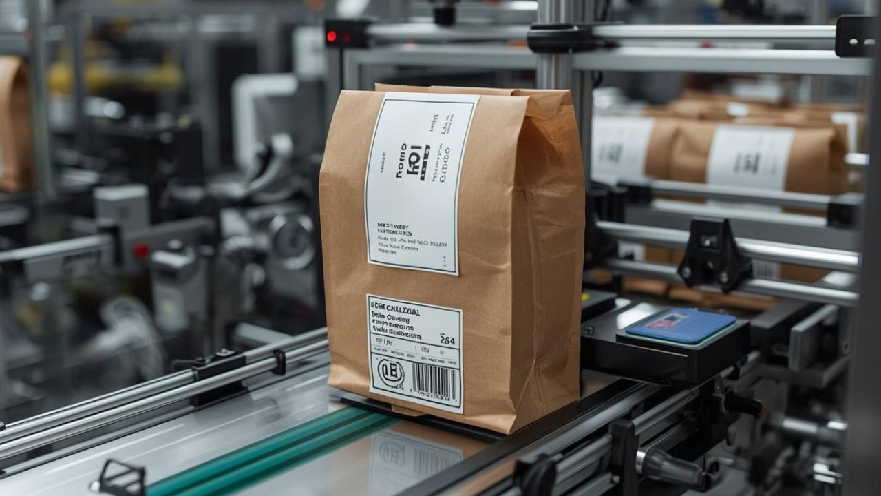
Lot codes, date codes, and serialization requirements are handled at the labeling station without adding a separate encoding step. Print-and-apply systems manage variable data at speeds up to 40 labels per minute. Continuous inkjet (CIJ) coders print directly on jars or lids at up to 508 meters per minute for high-speed date and lot coding applications.
QR codes and RFID integrate into the labeling station for serialization and full supply chain traceability. For regulated categories—pharmaceuticals, medical devices, certain food segments—this covers UDI and lot-level traceability requirements within the existing station footprint. No separate encoding station, no additional line length, no secondary handling step.
Ready to Build a Jar Line That Performs From Day One?
Jar line automation works when every station is designed as part of a system—not specified in isolation. Empty jar handling, filling accuracy, capping integrity, labeling on jars, and end-of-line packaging all depend on decisions made before the first piece of equipment is ordered. Getting those decisions right the first time is what separates lines that hit OEE targets within 18 months from those that don't.
If your product mix extends beyond jars, we also build horizontal flow wrapping systems, pre-made pouch machines, and vertical form fill seal lines using the same integration principles.At Wolf Packing, we engineer complete jar and container packaging systems, high-speed vffs machine configurations, and integrated lines built around your product, your throughput, and your facility. Contact us to talk through your line requirements and we'll help you build it right.